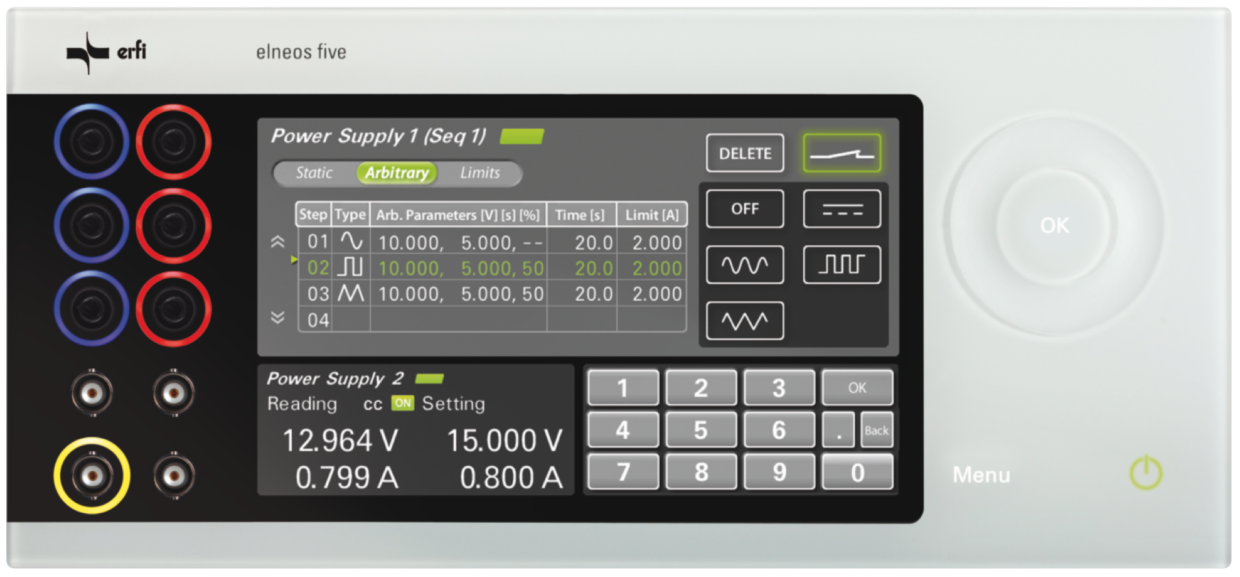
A table allows you to enter all waveforms and parameters. The evaluation of the curves is visualized by the data logger with recording function. Through the processor, two power arbitrary generators can process and display different sequences simultaneously. In addition, up to four measuring curves can be visualized simultaneously and further devices can be recorded and displayed. The data logger working in the background stores the data that can be read later.
Sequencer
Up to 100 segments per sequence can be entered or transferred via interface. The device can process up to 10 different sequences. Each sequence can be assigned to any arbitrary power arbitrator, which then executes the composite waveform. The segments in a sequence have different AC parameters: waveforms, period and amplitude. In addition, DC parameters can be defined per segment.
The sequencer allows you to cascade waveforms with different frequencies. The signals can thus be sequenced and mapped. The dynamics of the new measurement card enables the simulation of almost all signal forms.
Application areas
1) Simulation of brownout voltage drop for testing the reset circuit of a processor.
2) Several supply voltages, which rise successively when switched on and fall off again when switching off (power sequencing).
3) Superimposition of an artificial mains hum on the DC supply of a test object for measuring the PSRR (power supply rejection ratio). The term provides information about the extent to which the output voltage of an amplifier changes when its supply voltage changes. For operational amplifiers, the term PSRR is used in the technical data sheets.
4) Simulation of the on-board voltage dip of a car during startup. The available standard signal forms can be programmed by us or made available on request by us.
Display quality
Standard waveforms: sine, rectangle, triangle;
Duty cycle: variable;
Frequency: all waveforms up to 250 Hz;
Sequencer: allows different waveforms with different frequencies cascading.
Segments
Segments: 100 pieces can be edited directly on the device;
Per segment: waveform, period, amplitude, duty cycle and superimposed DC parameters with start and end value (U and I);
Limit values and measured value representation
Limit values: limits of all measured values programmable;
Measured value display: X-Y-graph can be called up and scaled by 2 finger gestures, ideal for long-term measurements;
Exit and entrance
Digital output: if the measured values are exceeded or undercut, a digital output is triggered;
Digital input: start of the measurement by trigger pulse of the input (edge control);
Data logger
The 4-channel mode enables the storage of 2000 measured values per channel. The values are graphically available and readable via interface.